
Main user interface
- Product Code: Main user interface
- Availability: 2-3 Days
The main menu
This is the main area for the most important basic functions and the sound settings of each channel.
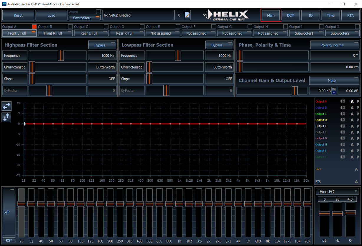
This menu is functionally divided into different areas, which are described below.
1. Data management, setting management and navigation

The upper area of the menu covers three different functions:
- Data management – load and save of afpx-files
- Setting management – creating, copying, selecting, naming and erasing of settings as well as editing of setting-specific notes
- Navigation – this is used to switch between the various configuration pages of the DSP PC-Tool. These control elements are global and accessible from all configuration pages .
1.1 Dateimanagement

„Load”
Clicking on this button opens a dialog that allows to open and load an existing afpx-file including all the adjustments contained into the connected device.
Note: All parameters can only be adopted if the opened afpx file was created with the same device as the one that is currently connected to the DSP PC-Tool. Otherwise it may happen that the transfer of the parameters is incomplete.
Save&Store
The "Save & Store" button carries out two processes with one click - on one hand, the current settings and parameters are stored in an afpx file on the computer, and on the other hand, the same data is permanently transferred to the connected device in the selected memory location.
Note: A lightened red “LED” on the button indicates that changes that have been made to the setting are not saved yet!
Note: If you make changes to a setting and do not save them by clicking on “Save & Store”, they will be lost when the device is restarted.
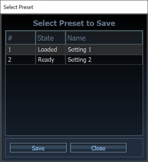
The dialog for selecting the memory location of a setting to be saved differs depending on the connected device.
ACO devices (with or without DIRECTOR)
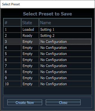
Here you can either overwrite existing settings or create new settings.
There are two storage locations available here.
Non ACO devices with DIRECTOR
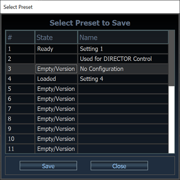
Here you can overwrite existing settings and re-allocated memory locations that are marked with "Empty / Version". Storage location 2 is not used due to internal dependencies in connection with the DIRECTOR.
Overwrite
If you check the “Overwrite” control box, you will not be asked for a file name when you save a setting again. The previously selected file will now be overwritten each time you click “Save & Store”.
1.2 Setting management

Reset
A click on the "Reset" button opens a dialog which enables various areas of the current setting to be reset.
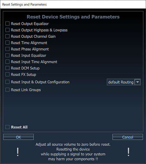
Caution: Resetting certain adjustments can lead to a sudden change in volume and / or incorrect filter configurations. Therefore, make sure to set the volume of all sources to minimum before resetting parameters.
Note: A reset via this button does not trigger a factory reset as this would be the case using the "Control" button on the device - the reset only affects the selected parameters of the currently loaded setting.
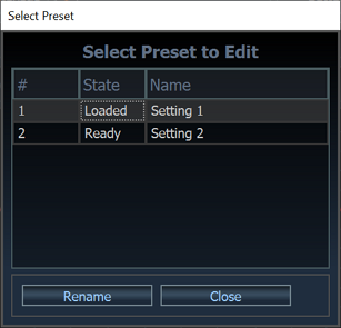
Create, copy, switch, rename and delete settings
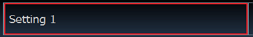
Clicking on the name of the current setting opens a menu for further administration of the settings on the device..
The appearance and the range of functions can differ in three different ways:
ACO devices (with or without DIRECTOR)
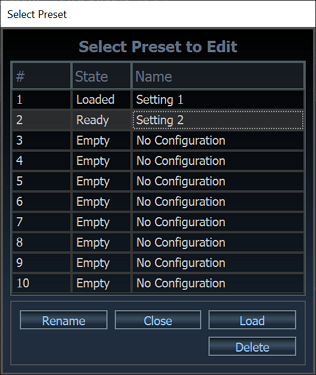
If you select a memory location with an already existing setting, you can either load the setting (i.e. switch to it), rename it or delete it. Note: the currently active setup cannot be deleted
If you select an empty memory location, you have the option of creating a new setting based on the active setting (“Copy”) or creating a setting with the basic adjustmenst (“New”).
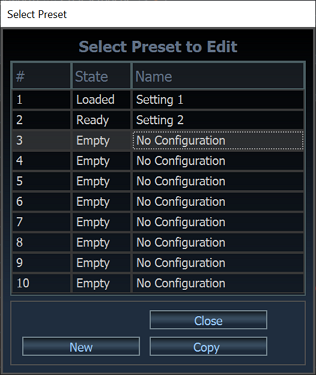
Non ACO devices without DIRECTOR
If you operate a device without the ACO platform, you have the option of changing the names of the two available settings in this menu. Settings cannot be deleted or recreated here, as the two available memory locations are always occupied by a setting.
Non ACO devices with DIRECTOR
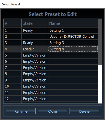
If you are connected to a non ACO device via a DIRECTOR, it is possible to rename or delete the settings from memory location 3 onwards. Storage space 2 is not used due to internal dependencies in connection with the DIRECTOR. In this constellation, new settings are created exclusively via the “Save & Store” button.
Notes

You can add a separate note for each setting. Here, for example, comments on the connection of the device or the latest changes to the setting can be recorded.
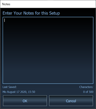
The “Last Saved” display informs about the last saving date of the setting.
Note: These notes are also included in the afpx-files that are saved on the computer.
.
1.3 Navigation
The various menus of the device and sound configuration can be accessed via these buttons. The scope of the main navigation can vary depending on the device type and the selected configuration method
View without VCP:

View with VCP:

Main / Outputs
This button always takes you back to this page. The designation “Main” changes to “Outputs” in VCP mode - the functional scope of the linked menu remains identical, however.
Virtual
This button only appears in VCP mode. Here you configure the virtual channels.
DCM
This button takes you to the “Device Configuration Menu” - here you can adjust device-specific settings, configure signal switchings and adapt the basic settings of the DSP PC tool. DCM
(S)FX (optional)
This button only appears on ACO-capable devices and the MATCH UP 7 BMW / DSP. It leads to the configuration menu of the sound effects. You can find more information about this here : SFX
IO – Input & Output
This button leads you to the configuration of the inputs and outputs. The input signals are assigned to the output channels here. A submenu takes you to the view of the input EQ and the ISA.
Time
This button takes you to the time alignment overview page - more information can be found here: Phase and time alignment
RTA
This button opens the “Real Time Analyzer” as a separate window. This window always remains in the foreground and can thus be used while adjusting the EQ. More information about the RTA can be found here : RTA
2. Channel selection
2.1 Overview

The channel selection is represented by a horizontal list. The labelling of the buttons is divided into two parts:
- The fixed name of the channel, for example “Output A” or “Amp Out A”
- The changeable assignment of the output, for example “Front L High” or “Rear L Full”

Note: A quick selection of the channels is possible using the function keys F1 - F12. If the “shift2 key is pressed at the same time, the corresponding “Channel + 10” will be selected.
2.2 Linking of channels
Channels can be linked to one another by clicking on the control box next to the fixed channel name. Through this link, various settings can be linked to one another across selected channels. The linking of the high and low pass filters is always “absolute” (which means that the linked channels always have identical filter settings). In the settings for the equalizer and the gain, you can select in the DCM menu whether the linking should be "absolute" or "relative". Check the DCM menu for further information: DCM.

Here’s an example – in this case the channel “Output A” is selected and it is linked to the channels “Output C” and “Output E”.
2.3 Copying of channel adjustments
The DSP PC-Tool offers the possibility of copying individual adjustments from one channel to the other. To use this function, mark the “source” channel from which the adjustments are to be adopted and right-click on the “target” channel to which the settings are to be transferred.
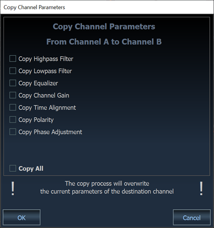
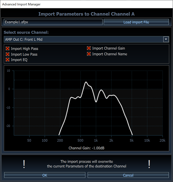
A dialog opens in which you can select which parameters shall be adopted.
2.3 Importing channel adjustments
With the “Advanced Import Manager” parameters from any afpx- or “REW EQ”-files can be adopted for the selected channel. The dialog opens by right-clicking on the respective channel or by pressing the “i” key.
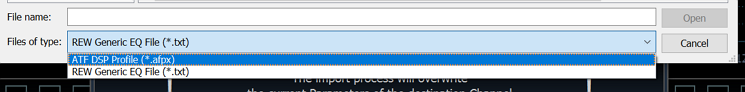
Note: In order to be able to select "REW EQ" files, the file filter must be set to "REW Generic EQ File" in the "Load import File" dialog:
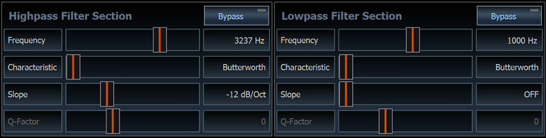
3. High and low pass filter adjustments
The functionality and the configuration of the high and low pass filters is described here.
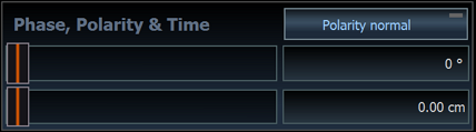
4. Phase, polarity and time alignment
The functionality and the configuration of the adjustments is described here.
5. Channel gain & output level
This section of the “Main” menu seems self-explanatory, but an incorrect setting can not only degrade the sound quality, but it can also seriously damage your speakers! Assuming that you have correctly adjusted the gain of your entire signal chain (radio DSP amplifier), you primarily need the output level control to compensate for the different efficiencies of your loudspeakers:
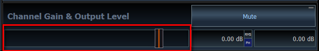
In practice, the slider should only be moved a few decibels. The set value of the gain is shown in the right "dB" display:
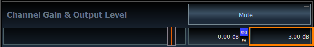
The resolution of the slider can be changed in the DCM menu between 0.10 dB, 0.25 dB, 0.50 dB or 1.00 dB. The default value is 0.25 dB, whereby in practice a resolution of "1.00 dB" or a maximum of "0.50 dB" is absolutely sufficient.
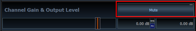
If you need to make major adjustments to the channel gain, first check your configuration for errors. Do not use the level control to mute a channel. For this purpose please use the “Mute” button:
If a signal is present on a channel, you will see a blue bar in the slider that indicates the current level. The corresponding dB value is displayed in the orange marked field.
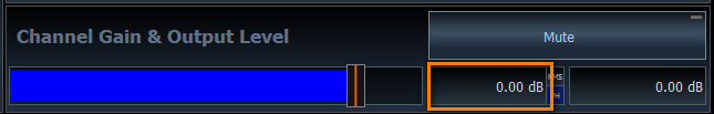
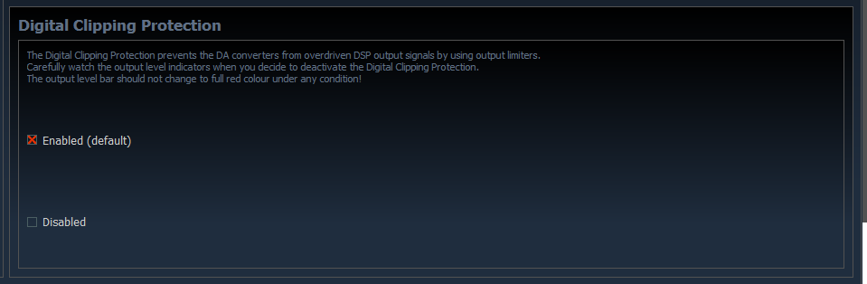
It becomes critical when the colour of the bar changes from blue to red and values greater than "0.00 dB" are indicated in the dB display next to the bar. In this case, the output will be overdriven and produce distortion that could damage your speakers. That’s why a “Digital Clipping Protection” is implemented in the signal path of each of our DSP products by default, which limits the maximum THD at the output to uncritical values below 1 %. You can deactivate this protective feature in the DCM menu, but then you should be aware that very strong distortions can occur if the output is overdriven:
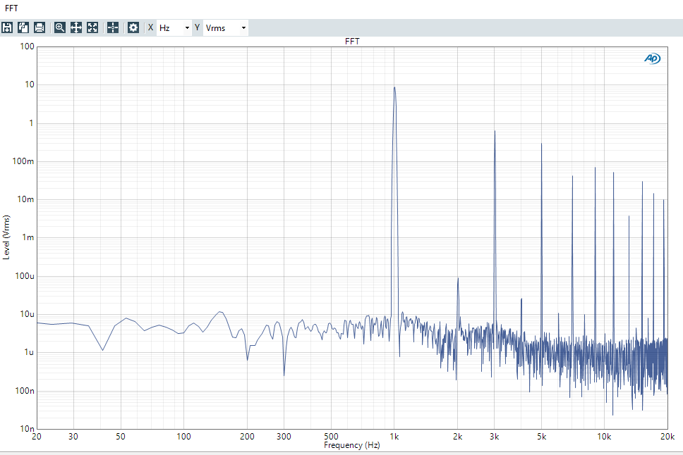
A distortion measurement clearly shows the effect when a digital system is overdriven. Normally the lowest distortion factor is achieved close to full scale (0 dBFS), but as soon as you exceed this “magic limit”, the distortion increases extremely. In the following example you can see the FFT spectrum of a 1 kHz tone with all its distortion harmonics at 2 kHz, 3 kHz, 4 kHz, 5 kHz and so on. In this case the system was only overdriven by 1dB – nevertheless the THD already reaches almost 10 %:
This enormous additional energy has to be absorbed by the tweeter, which is simply not designed for this and will burn very quickly! So we strongly recommend: leave the "Digital Clipping Protection" activated! You should avoid digital overload under all circumstances, even if it only occurs for a very short time. Especially with dynamic music it is difficult to reliably detect peak values. For this very reason the DSP PC-Tool offers the "Peak Hold" function, which you can activate by clicking on the small "PH" button:
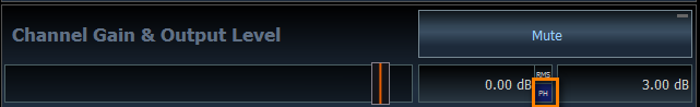
Now the highest signal level will be "frozen" for two seconds, which makes it easier to recognize peak levels in music and allows you to more reliably approach the magical "0 dB limit" when adjusting the channel gain.
6. The equalizer
The functionality of the EQ as well as all control elements for its display of the amplitude and phase response is explained here.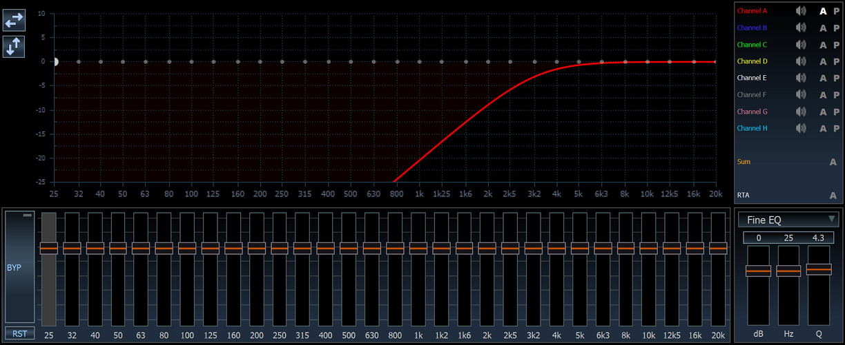


")
")
